
Highway Guardrail Installation Conditions: Clear Zone, Roadside Risk and Protection Levels
August 9, 2026
How to Choose Guardrails for Coastal and Highly Corrosive Environments
September 6, 2026
Quick Answer
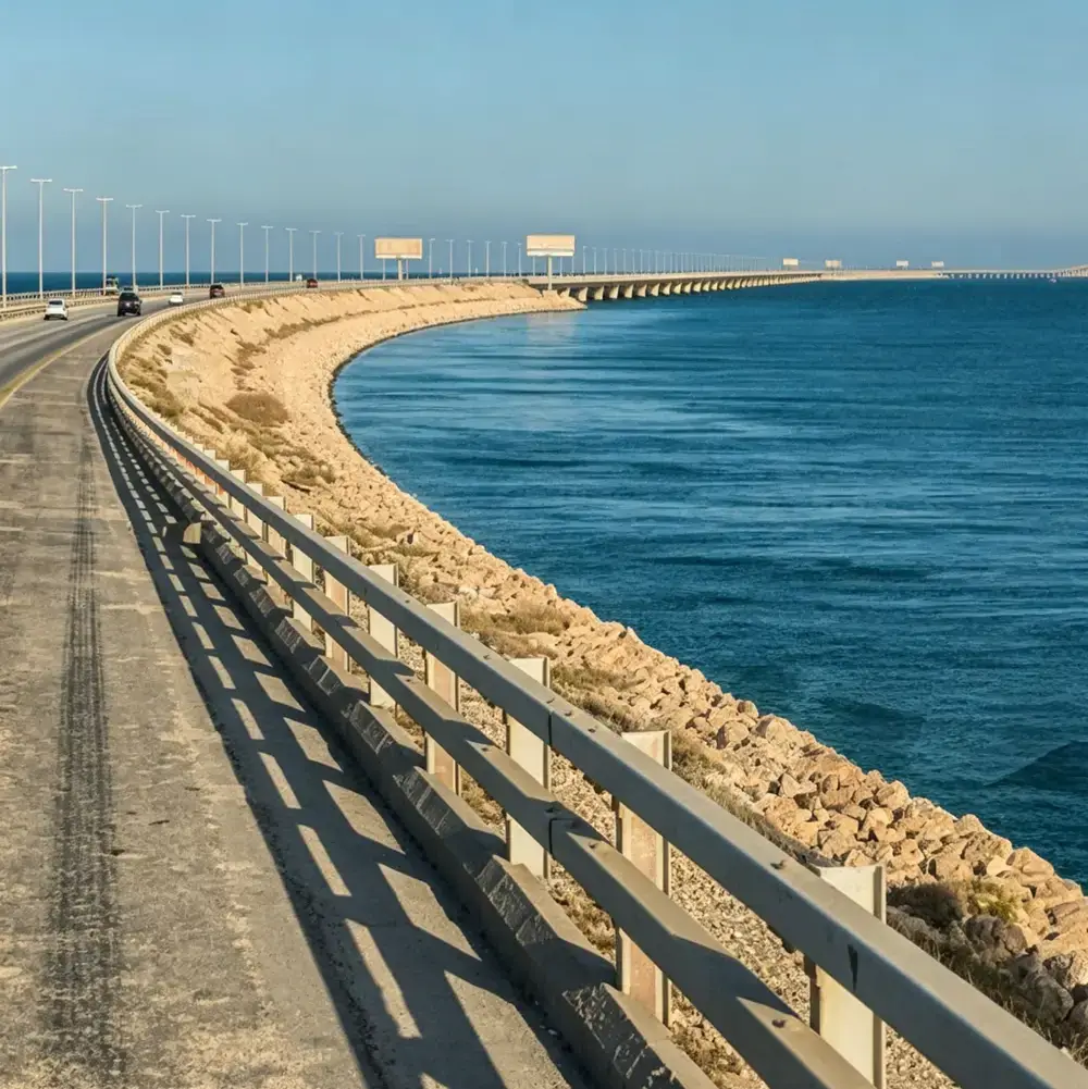
Bridge and waterfront guardrails cannot be judged by the shape of a beam, the steel grade or the surface color alone. The project must first define the protection function: vehicle containment, pedestrian fall protection or waterfront boundary control.
Vehicle bridge barriers must be designed or tested as complete systems. Beams, posts, blockouts, brackets, bolts, terminals, bridge connections, transitions and installation conditions can all affect the final performance.
Anchorage must also be designed with the bridge deck or concrete foundation. Base-plate dimensions, anchor layout, cast-in sleeves, concrete strength, reinforcement, deck thickness and edge distance should be confirmed from the approved drawings and design loads.
1. Start by Classifying the Guardrail
1.1 Vehicle bridge barriers
Vehicle bridge barriers are installed at the edge of a roadway, on the outside of a bridge deck or in a median. Their primary function is to contain an errant vehicle and prevent it from leaving the bridge, entering opposing traffic or striking hazards below.
The safety performance of this type of barrier belongs to the complete system. A single W-beam panel, post or bolt assembly should not be marketed as a certified crash-protection level by itself.
1.2 Pedestrian and cyclist railings
Pedestrian and cyclist railings are used on bridge sidewalks, cycleways, waterfront paths and public platforms. Their main requirements usually include fall prevention, continuous handrails, edge protection, clear width, opening size and resistance to climbing.
For U.S. public facilities, the 2010 ADA Standards address handrail height, clearance, edge protection and accessible routes. ADA requirements apply to projects covered by those rules and do not replace the building, municipal or accessibility requirements of other countries or regions. 2010 ADA Standards for Accessible Design
1.3 Waterfront and landscape boundary railings
River, canal, park and scenic-area railings typically provide boundary control, pedestrian guidance and fall protection. If the railing is close to a traffic lane, bridge edge, deep water or a significant level difference, the project must reassess vehicle departure, pedestrian fall and structural failure risks. It should not be treated as a purely decorative railing.
2. Match the Project to the Applicable Requirements
| Project environment | Main safety issue | Standards and information to verify |
|---|---|---|
| Road bridge roadway edge | Vehicle departure, intrusion and barrier deflection | Local bridge-barrier design rules, crash-test standard and approved drawings |
| Expressway or high-speed bridge | High-speed and heavy-vehicle impact | Applicable JTG B05-01, JTG D81, MASH or EN 1317 (EN 1317 series) requirements |
| Urban bridge or waterfront road | Mixed vehicle, pedestrian and cyclist use | Road-safety, bridge-design and accessibility requirements |
| Park, riverbank or canal path | Falls, child passage and wheelchair access | Local building, municipal, accessibility and public-space rules |
| Port, seaside or salt-spray environment | Corrosion at anchors, welds and coatings | Corrosivity classification, material specification and maintenance plan |
For projects in China, the main references normally include JTG D81—2017, Design Specifications for Highway Safety Facilities, and JTG B05-01—2013, Roadside Safety Performance Evaluation Standard. JTG D81 addresses bridge-barrier placement, containment levels, dynamic deflection, deck connections and transitions. JTG D81—2017 reference file
For U.S. projects, the design team normally needs to verify FHWA, AASHTO bridge-design and MASH requirements. FHWA bridge-design guidance calls for bridge railings that meet the project’s crash-test requirements and for approach railings to connect to the bridge railing through details capable of developing the required strength. FHWA bridge structural design guidance
For European projects, the target country and project specification should be checked against the EN 1317 series. In the United Kingdom, CD 377, Requirements for Road Restraint Systems, covers vehicle restraint systems, vehicle parapets, pedestrian parapets, terminals and transitions. It uses a site-specific risk-assessment process to establish the required performance. UK National Highways CD 377
Level names from different standards cannot be treated as direct equivalents. Buyers should confirm the standard edition, test vehicles, speed, angle, evaluation criteria, system configuration and approval body.
3. Containment Levels Apply to the Complete System
A vehicle containment level is not the thickness of a beam, the strength of the steel or a product name. A complete system normally includes:
- beam or rail;
- posts;
- blockouts, brackets or backing plates;
- splice bolts and connection bolts;
- terminals and transitions;
- bridge base plates, anchors or cast-in sleeves; and
- the foundation, bridge deck and installation conditions.
If the post section, post spacing, blockout, bolt quantity, mounting height or bridge connection changes, the original crash-test result cannot automatically be reused. Extending a roadside barrier directly onto a bridge deck without a designed transition can also create a local stiffness change or vehicle snagging risk.
Bridge barriers must also be checked for post-impact dynamic deflection and vehicle roll or intrusion. The deflected system must not enter the bridge edge, hazards below or another protected structure. JTG D81—2017 considers the hazard outside the bridge, bridge height, traffic volume, operating speed and vehicle composition when selecting the bridge-barrier containment level.
4. Understand the Barrier Load Path
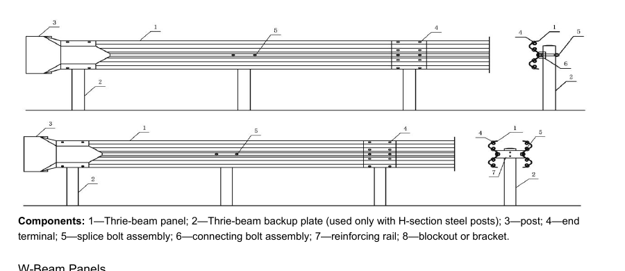
When a bridge barrier receives vehicle impact or another design load, the force must travel through a continuous load path:
Beam or rail → blockout or bracket → post → base plate or sleeve → anchor or embedded component → deck and concrete structure
Any weak link can reduce the performance of the system. Technical confirmation and quotation should therefore address at least:
- barrier height and rail section;
- post section, length and spacing;
- blockout, bracket and connection-bolt models;
- base-plate dimensions and anchor layout;
- deck thickness and concrete strength;
- reinforcement location, edge distance and expansion joints; and
- drainage channels, scuppers and maintenance access.
5. Common Bridge-Barrier Anchorage Methods
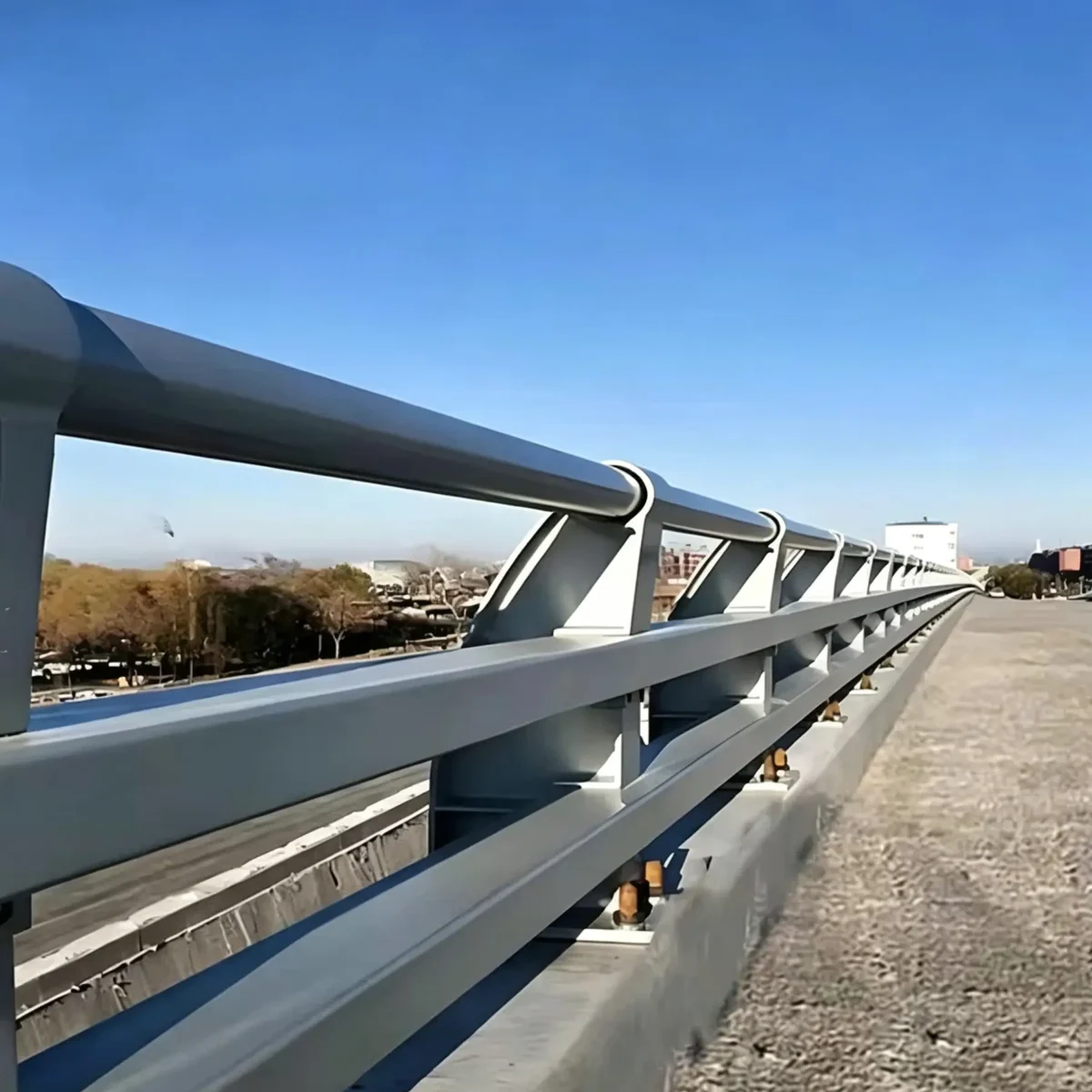
5.1 Direct embedment
The post is embedded directly into the deck edge or concrete structure. This method can provide good continuity when the structural thickness, construction conditions and embedment depth meet the design requirements. The trade-off is more difficult replacement and repair.
5.2 Cast-in sleeves
Sleeves are reserved during deck or foundation casting, and the posts are inserted and fixed during later installation. This supports modular installation and replacement, but sleeve position, depth, grouting and surrounding reinforcement must be controlled accurately.
5.3 Base plate with anchor bolts
The post is welded to a base plate and fixed to the concrete structure with anchor bolts. This method is often considered for thin decks, bridge rehabilitation or projects that require easier replacement. The base plate, anchors, concrete edge distance and local deck forces must still be checked by the structural designer.
5.4 Chemical anchors or special bases for rehabilitation
Existing-bridge rehabilitation may use a project-approved chemical anchor or special base. FHWA guidance emphasizes that anchors must be installed in accordance with the manufacturer’s instructions. For bridge barriers exposed to water, salts and traffic vibration, anchor corrosion can reduce the connection capacity between the barrier and the deck. FHWA bridge-barrier anchorage and corrosion reference
There is no universal anchor diameter, embedment depth or base-plate dimension for every bridge. The final details must be based on the design load, deck structure, concrete strength, reinforcement, edge distance and applicable local requirements.
6. Do Not Omit Transitions, Expansion Joints or Drainage
6.1 Roadside-to-bridge transitions
Bridge barriers and approach barriers can have different stiffness, sections, post spacing and heights. A direct rigid connection between two different systems can create a snagging hazard, a pocket effect or a sudden stiffness change. The transition should be designed to the applicable project standard.
6.2 Bridge expansion joints
Rails, base plates and connection components must not restrain normal bridge movement. Expansion-joint locations should be coordinated with rail splices, sleeves, base plates and maintenance space.
6.3 Drainage and standing water
Deck edges, scuppers and drainage channels can become high-corrosion locations for anchors, base plates and welds. The design should limit standing water, sediment and salt retention and provide access for inspection and cleaning.
7. Materials and Corrosion Protection
7.1 Q235 and Q355 carbon steel
These grades are suitable for many standard bridge, road and landscape projects and provide a practical balance of strength, fabrication and cost. The final grade and thickness should follow the project drawings and purchasing specification.
7.2 304 and 316 stainless steel
304 and 316 stainless steel can be considered where appearance and corrosion resistance are important. Seaside, marina, salt-spray and high-corrosion projects require a stricter material and maintenance review; the material name alone should not be used to promise a fixed service life.
7.3 Hot-dip galvanizing
Hot-dip galvanizing is widely used for outdoor steelwork. ISO 1461:2022 specifies general properties and test methods for hot-dip galvanized coatings on fabricated iron and steel articles. ISO 1461:2022
7.4 Powder coating and duplex systems
Powder coating is useful where a project requires a specific architectural color or visual identity. A duplex system, such as galvanized steel with a colored topcoat, combines a zinc base layer with a visible finish. The purchase specification should identify surface preparation, coating system, dry-film thickness, adhesion, color and field-repair method.
ISO 12944-2 classifies atmospheric, freshwater, marine and immersion environments and can be used as an environmental basis for coating-system selection. ISO 12944-2:2017
Surface treatment is not a crash-protection level. Galvanizing, powder coating and stainless steel address durability and appearance; none of them alone proves that a barrier has passed a crash test.
8. What Should Be Checked at Project Acceptance?
| Acceptance item | What to verify |
|---|---|
| Design documents | Layout, section, post spacing, anchorage and transition drawings |
| System configuration | Beam, post, blockout, bracket, bolts, terminal and connection consistency |
| Materials | Steel grade, thickness, mill certificates and batch traceability |
| Welding and fabrication | Welds, holes, cuts, bends and visual quality |
| Anchorage | Anchor size, embedment, edge distance, torque, grouting and concrete condition |
| Corrosion protection | Zinc thickness, coating thickness, adhesion, color and repair records |
| Dimensions | Height, alignment, spacing, rail splices and expansion-joint position |
| Installation | Post plumbness, bolt orientation, tightening and field markings |
| Performance evidence | Crash-test report, system approval or project acceptance basis |
| Handover documents | Installation guide, inspection reports, production records, packing marks and maintenance advice |
9. Information to Provide Before Quotation
To avoid a mismatch between quotation and installation, the buyer should provide:
1. project country and location; 2. bridge, river, canal, park, marina or urban-road application; 3. vehicle, pedestrian, cyclist or mixed use; 4. design speed, traffic volume and target containment level; 5. existing deck or concrete-foundation drawings; 6. concrete strength, reinforcement location and available edge distance; 7. expansion joints, drainage and maintenance access; 8. material, corrosion-protection, color and documentation requirements; and 9. the acceptance criteria of the owner or local authority.
Frequently Asked Questions
Can a standard roadside barrier be used directly as a bridge barrier?
Not automatically. Bridge edges, hazards below, deck structure and post-impact deflection are different from ordinary roadside conditions. The complete system and approved project drawings must be checked.
Can one W-beam panel be marketed as an EN 1317 or MASH product?
No. EN 1317 and MASH performance applies to a complete tested or approved system, including beams, posts, connections, terminals, foundations and installation conditions.
Does a larger anchor automatically make the barrier safer?
Not necessarily. Anchor capacity must match the base plate, concrete, reinforcement, edge distance, load direction and local deck behavior.
Does a galvanized barrier require no maintenance?
No. Drainage, salts, sediment, bolted joints and welds can all affect durability. Coating inspection and routine cleaning remain important.
Conclusion
The safety of a bridge or waterfront guardrail depends on the complete system, the deck connection, the project risk and the installation conditions—not on the appearance of one beam.
Vehicle bridge barriers should be based on applicable standards, a complete system and approved project documents. Pedestrian and waterfront railings should address fall prevention, access and maintenance. Anchorage, transitions, expansion joints and drainage determine whether the system can retain its intended function over time.
China Guardrail can review project drawings, deck conditions, environmental exposure and local acceptance requirements to configure beam sections, posts, connections, anchorage, surface protection and supporting documents. Final containment levels, structural dimensions and anchorage details should be confirmed by the project designer, owner and relevant authority.
Technical References
- JTG D81—2017, Design Specifications for Highway Safety Facilities;
- JTG B05-01—2013, Roadside Safety Performance Evaluation Standard;
- FHWA bridge structural design and bridge-railing guidance;
- UK National Highways CD 377, Requirements for Road Restraint Systems;
- ISO 1461:2022;
- ISO 12944-2:2017; and
- 2010 ADA Standards for Accessible Design.
Standards and Sources Referenced
The specifications and requirements discussed in this article are drawn from the following published standards and official guidance:
- AASHTO Publications — AASHTO’s official standards and publications catalogue. https://store.transportation.org/
- FHWA Publication FHWA-HRT-14-071 — Research publication on bridge and structure safety hardware. https://www.fhwa.dot.gov/publications/research/infrastructure/structures/14071/index.cfm
- CEN/CENELEC — European standards body responsible for the EN 1317 series. https://www.cencenelec.eu/
- Transportation Research Board — National research body behind NCHRP roadside-safety research. https://www.trb.org/